The “Confusion” over PAPI Elevation Angles
Why is there always a deviation between flight-calibration data and on-ground measured data? Is it an equipment problem, or an operational error? To answer this question, we must first re-understand the PAPI elevation angle.
Simply put, the PAPI elevation angle is the physical angle between the centreline of the light beam (the red/white transition line) and the local datum horizontal plane. In practice, however, flight calibration (the flight perspective) and on-ground inclinometers (the physical perspective) adopt different measurement references and mechanisms, so the same physical angle presents different values in different scenarios.
Such numerical differences often bring confusion. This article aims to build a complete and logical picture for the reader by sorting out the specific meanings of the four elevation angles and their logical relationships.

Understanding the Four PAPI Elevation Angles
Design Elevation Angle
The theoretical angle gradient set in accordance with the Technical Standards for Airfield Area of Civil Airports and the design requirements of the specific project.
Nature: the “innate genetic code”.
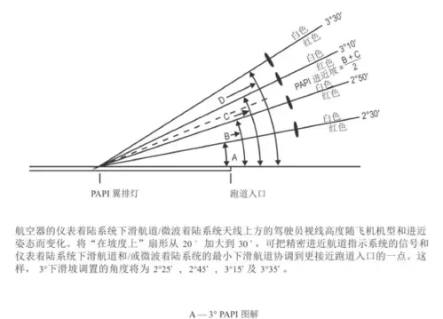
Flight-Calibration Elevation Angle
The PAPI angle measured from the flight perspective by a calibration aircraft or UAV equipped with precision instruments in accordance with the standard calibration flight procedures.
Nature: the “final arbiter”. It is the only statutory basis for judging whether the PAPI light beam is qualified.
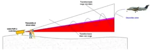
On-Ground Measurement Elevation Angle (External Inclinometer)
The mechanical inclination angle measured on the reference plane from the physical perspective by inspection and maintenance personnel using a high-precision inclinometer (which must meet the relevant accuracy standards).
Nature: the “maintenance benchmark”. It is a substitute measurement used in routine maintenance because the light beam cannot be measured directly.
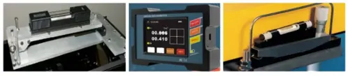
This angle can also be measured by other means, such as theodolites and total stations:

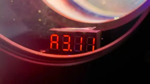
PAPI Built-In Elevation Display Angle
The value presented on the digital display by the angle sensor integrated inside the luminaire, from the equipment self-check perspective.
Nature: “status monitoring”, used for quick inspection and safety protection.
Building the Logic: How the Four Angles Map and Lock
Installation phase (based on the design elevation angle): the installation contractor performs initial installation and coarse adjustment to the design gradient (e.g., 2°25′).
Verification phase (flight-calibration elevation angle): the aircraft verifies in the air; if the calibration passes, the light path is proved correct.
Locking phase (establishing the ground standard): once calibration has passed, the condition at the time of passing is locked in immediately. Key action: the reading taken with the external inclinometer at that very moment becomes the “subsequent maintenance standard value (locked value)” — the baseline anchor.
Monitoring phase (based on the built-in/external elevation angle): daily inspections refer to the built-in display (for reference); periodic checks use external measurement (maintenance standard).
Correction phase: if the deviation between the external measurement and the “locked value” exceeds the allowable range, the cause (settlement, impact, etc.) must be identified and corrected; if necessary, a new calibration flight must be requested.
An Everyday Analogy
If the above is hard to follow, imagine using an air conditioner on a summer day:
Design elevation angle ≈ the recommended comfort temperature (26 °C)
Experts recommend setting the room to 26 °C for the best comfort. That is the design target.
Flight-calibration elevation angle ≈ the actual coolness you feel
You step into the room and think: “Well, this temperature is just right — neither too hot nor too cold.” That is the ultimate experience standard.
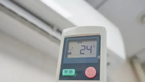
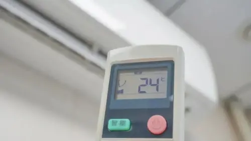
External inclinometer elevation angle ≈ the number shown on the remote control (24 °C)
To give you that “just right” coolness, the remote control must be set to 24 °C. From then on you only need to trust the 24 °C on the remote: whenever it reads 24 °C, you know it will be comfortable.
Built-in display elevation angle ≈ the operation light on the AC panel
A glance from a distance tells whether the AC is running; if the panel shows an “E1” error code, the air conditioner has broken down.
Practical Applications of and Deviations among the Four Elevation Angles
Design elevation angle — the installation reference
Application: used only for engineering installation or initial re-setting, to ensure that the relative gradient relationship among the four luminaires is correct.
Flight-calibration elevation angle — the acceptance criterion and calibration source
Application 1: it gives the final verdict on whether the PAPI calibration result is qualified. According to flight-calibration requirements, the deviation between the flight-calibration elevation angle and the design elevation angle shall be within ±0.2° (refer to FAA Order 8200.1D).
Application 2: “reverse calibration”. Its purpose is to confirm that the value measured by the external inclinometer (e.g., 2°24′) is valid, granting legitimacy to the on-ground measurement value.
On-ground external inclinometer elevation angle — the standard for routine maintenance
Application 1: linked with the flight-calibration result to establish the “maintenance standard value”.
Application 2: periodic measurement, used to determine whether the PAPI elevation angle has physically drifted and whether the deviation exceeds the allowable range — namely ±2′ as the target value at initial commissioning and ±6′ as the target value during service (refer to MH/T 5083-2024). For this reason, the accuracy required of the external inclinometer also varies at different stages.
PAPI built-in elevation display angle — monitoring and protection
Application 1: excessive-tilt protection. When a luminaire remains tilted beyond the threshold, the power is cut off automatically on the basis of this value to prevent the emission of misleading guidance signals.
Application 2: non-contact monitoring. Obvious anomalies can be detected quickly through the PAPI monitoring system or routine patrols. The built-in inclinometer display must be accurate to within ±3′ (refer to FAA AC 150/5345-28H).
Conclusion
The core of PAPI elevation-angle maintenance is not to chase identical numbers among the four angles, but to understand the locking and mapping relationships between them. Rooted in the design standard, anchored to the calibration conclusion, using external measurement as the lever and heeding the built-in protection logic — this is how we safeguard the safe take-off and landing of aircraft.
If you have any suggestions or ideas, please leave a comment below to join the discussion and help safeguard flight safety.

References:
l MH 5001-2021 Technical Standards for Airfield Area of Civil Airports
l MH/T 5083-2024 Maintenance Regulations for AGL Systems of Civil Airports
l ICAO Annex 14, Volume 2 – Aerodromes
l ICAO Doc 9157, Part 4 – Aerodrome Design Manual: Visual Aids
l FAA AC 150/5345-28H PAPI Systems
l FAA Order 8200.1D Flight Inspection Manual